Home >> Resources >> Technical Articles
Cryogenic Insulation Considerations for LNG Receiving Terminals
Why cryogenic insulation at -162°C is a system engineering challenge rather than simply a material selection issue
Thermal bridge risks at valves, flanges, pipe supports, and instrument connections
How aerogel insulation blankets may be evaluated for complex cryogenic piping nodes
Key considerations for vapor barriers, external jacketing, pipe movement, and installation quality
How Airgeltech supports LNG cryogenic insulation projects through material selection and technical assistance
LNG receiving terminals operate under some of the most demanding insulation conditions in the energy industry.
With process temperatures reaching approximately -162°C (-260°F), cryogenic pipelines must maintain reliable thermal performance while managing heat ingress, moisture migration, thermal contraction, complex piping geometries, mechanical movement, and long-term environmental exposure.
Unlike conventional hot-service insulation, cryogenic insulation must also prevent ambient moisture from reaching surfaces operating far below the dew point. A weakness in the vapor barrier, insulation joint, equipment penetration, or termination detail can create a path for moisture ingress and increase the risk of condensation, frost, ice formation, and long-term deterioration.
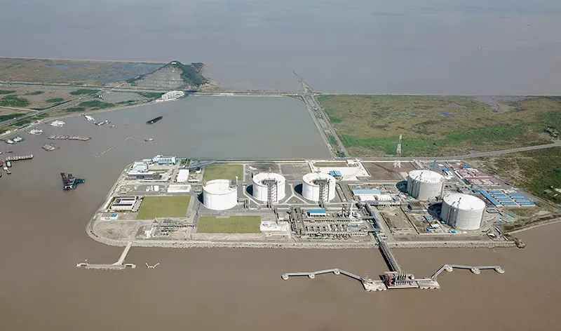
Using the Shanghai LNG Receiving Terminal Expansion Project as a publicly reported industry reference, this article examines the principal insulation challenges associated with large LNG facilities and discusses the potential role of aerogel insulation blankets in modern cryogenic insulation systems.
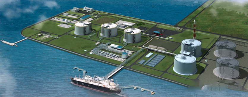
Located at Yangshan Deep-Water Port, the Shanghai LNG Receiving Terminal Expansion Project is a major energy infrastructure development serving Shanghai and the surrounding region.
According to publicly available project information, the expanded terminal has a maximum natural gas delivery capacity of more than 50 million cubic meters per day. Its maximum regasification capacity increased from 1.04 million m³/h to 2.14 million m³/h, supporting more than 50% of Shanghai's natural gas demand.
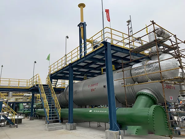
The terminal includes LNG transfer pipelines, SCV vaporizers, IFV vaporizers, BOG compressor systems, and extensive auxiliary process piping.
Because LNG is stored and transported at approximately -162°C, the integrity of the cryogenic insulation system is essential to the safe, efficient, and reliable operation of the facility.
For an LNG receiving terminal, insulation is not simply a covering applied around a pipe. It is an engineered system that helps control heat transfer, moisture ingress, surface conditions, and long-term operating reliability.
Poor cryogenic insulation performance may contribute to:
Increased heat ingress into the LNG process system
Condensation, frost, or ice formation
Moisture penetration into the insulation assembly
Deterioration of insulation performance
Higher inspection and maintenance requirements
Increased lifecycle operating costs
Reduced reliability at valves, supports, and other critical nodes
The performance of the complete system depends not only on the thermal conductivity of the insulation material, but also on insulation thickness, layer arrangement, joint design, vapor barrier integrity, external jacketing, pipe movement accommodation, and installation workmanship.
As LNG infrastructure continues to expand worldwide, improving the reliability and durability of cryogenic insulation has become an important engineering priority.
For LNG facilities, the challenge is not limited to the extremely low operating temperature. The greater challenge is maintaining insulation performance throughout years of continuous operation while thermal movement, environmental moisture, maintenance activities, and complex geometries act on the system simultaneously.
When LNG flows through piping at approximately -162°C, the temperature difference between the process medium and the surrounding environment can exceed 180°C.
Under these conditions, several engineering issues require careful consideration.

Cryogenic pipelines contract as their temperature decreases.
The expected movement must be considered in the design of pipe supports, anchors, expansion arrangements, insulation joints, vapor barriers, and metal jacketing.
If the insulation assembly cannot accommodate the movement of the pipe, joints may open, flexible seals may become overstressed, external jacketing may deform, and vapor barrier continuity may be affected.
Cryogenic insulation therefore needs to function as part of a coordinated piping system rather than as an isolated material layer.
Straight pipe sections can generally be insulated with relatively uniform layers. The most demanding areas are usually the locations where geometry, mechanical loads, access requirements, and material transitions come together.
Typical high-risk locations include:
Valves
Flanges
Pipe supports
Anchors and guides
Instrument connections
Equipment interfaces
Expansion transitions
Insulation termination points
Metallic components and discontinuities in the insulation layer can create localized heat-transfer paths. These thermal bridges may result in lower external surface temperatures and a greater risk of condensation or frost formation.
Ambient air contains moisture. When that moisture reaches a sufficiently cold surface, condensation occurs.
In a cryogenic system, condensed moisture may freeze and develop into frost or ice. This is why vapor control is a fundamental requirement in LNG insulation design.
Potential moisture-entry points include:
Damaged vapor barriers
Incomplete seals
Open insulation joints
Instrument penetrations
Jacketing seams
Pipe support interfaces
Poorly detailed termination areas
A hydrophobic insulation material can help reduce liquid-water absorption, but hydrophobicity alone does not replace a continuous and properly sealed vapor barrier system.
LNG receiving terminals are commonly located in coastal areas.
At Yangshan Deep-Water Port, outdoor equipment is exposed to high humidity, sea winds, salt-laden air, rain, temperature variation, and long-term weathering.
Under these conditions, thermal performance and moisture management must be considered together.
The external jacketing system must protect the insulation and vapor barrier from weather exposure, mechanical impact, maintenance activities, and environmental deterioration. Material compatibility and corrosion resistance also require careful evaluation.
LNG facilities are intended for long operating lives.
Cryogenic insulation systems may be exposed to:
Continuous low-temperature operation
Startup and shutdown cycles
Pipe contraction and expansion
Vibration
Environmental moisture
Mechanical impact
Inspection and maintenance activities
Local repair and reinstatement
Initial laboratory properties are important for material selection, but long-term engineering performance also depends on system design, construction quality, inspection procedures, and maintenance practices.
Cryogenic insulation is not simply a matter of selecting the material with the lowest thermal conductivity.
A reliable LNG insulation system requires the integration of several engineering disciplines and system components, including:
Thermal engineering calculations
Pipe stress and movement analysis
Insulation material selection
Insulation thickness determination
Multilayer joint design
Vapor barrier design
Pipe support and structural interface design
Weather-resistant external jacketing
Inspection and installation quality control
The insulation thickness should be determined according to the specific operating conditions of the project. Relevant inputs may include:
Process temperature
Pipe diameter
Ambient temperature
Relative humidity
Wind conditions
Target external surface temperature
Allowable heat flux
Available installation space
Applicable engineering standards
Particular design attention is generally required at LNG transfer pipelines, vaporizer connections, BOG compressor piping, valves, flanges, pipe supports, instrument penetrations, expansion areas, and insulation termination points.
These locations often determine the practical performance of the overall insulation system.
Publicly available information indicates that a new type of aerogel insulation blanket was used in LNG pipeline insulation work associated with the referenced project.
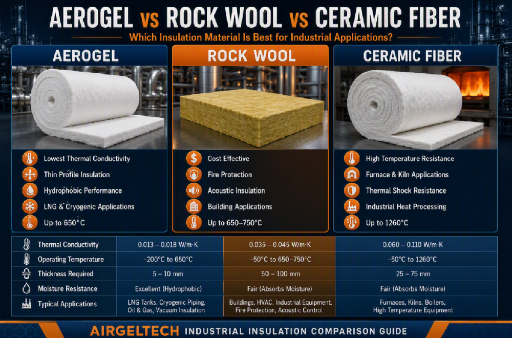
Aerogel insulation blankets are attracting attention in cryogenic applications because they combine low thermal conductivity with flexibility and a relatively compact insulation profile.
Their engineering value is not based on the assumption that aerogel should replace every conventional cryogenic material. Instead, aerogel may be considered as part of an engineered insulation system, especially where space is limited, geometry is complex, or thermal bridge control requires additional attention.

Silica aerogel contains a nanoporous structure that restricts heat transfer through the insulation layer.
In LNG piping systems, limiting heat ingress can help support stable cryogenic operating conditions and reduce unwanted heat flow into the process medium.
The actual performance of an insulation assembly must be evaluated through project-specific thermal calculations. It cannot be determined solely by the generic name of the material.
LNG facilities often contain densely arranged piping, valves, structural supports, instrumentation, and equipment connections.
In certain designs, aerogel insulation may help achieve the required thermal performance with a more compact insulation profile than some conventional alternatives.
This may be valuable in:
Congested process areas
Locations with restricted clearances
Pipe racks with limited spacing
Valve and flange assemblies
Equipment interfaces
Areas requiring improved access for inspection or maintenance
The final insulation thickness must still be confirmed through thermal calculations and relevant project requirements.
Flexible aerogel insulation blankets can be cut, layered, and fitted around complex geometries such as:
Valves
Flanges
Elbows
Tees
Reducers
Pipe supports
Instrument connections
Irregular equipment surfaces
This flexibility can improve conformity around components that may be difficult to insulate using rigid materials alone.
Good conformity may help reduce gaps and improve insulation continuity, but the result still depends on correct cutting, fitting, fastening, joint arrangement, vapor sealing, and external protection.
Valves, flanges, supports, instrument interfaces, and transitions are frequently among the most difficult parts of a cryogenic insulation system.
Aerogel blankets may be installed in multiple layers with staggered joints around these complex nodes. This approach can reduce the likelihood of continuous joint paths extending through the entire insulation thickness.
Aerogel insulation does not independently eliminate all thermal bridges or prevent every occurrence of condensation and frost. Effective control requires coordinated design of the insulation layers, support system, vapor barrier, penetrations, seals, and external jacketing.
Hydrophobic silica aerogel insulation can help limit liquid-water absorption within the insulation material.
This property may offer advantages in high-humidity environments, but it must not be treated as a substitute for vapor control.
At cryogenic temperatures, a properly designed and continuously sealed vapor barrier remains essential. All joints, penetrations, terminations, and repair areas require careful sealing to reduce moisture migration into the insulation system.
Some LNG valves, flanges, instruments, and equipment interfaces require periodic inspection or maintenance.
Flexible insulation materials may support removable or modular insulation concepts in certain locations. However, the design must balance:
Thermal continuity
Vapor tightness
Mechanical durability
Maintenance access
Ease of removal
Reliable reinstatement after inspection
Repeated removal and reinstallation should not be assumed to preserve system integrity unless the assembly has been specifically designed and inspected for that purpose.
Based on industry practice, aerogel insulation may be evaluated for the following LNG and cryogenic applications.
Aerogel insulation may be incorporated into LNG transfer piping systems to reduce heat ingress or achieve a more compact insulation structure.
Uniform layer thickness, staggered joints, and controlled compression are important installation considerations.
Valves and flanges combine irregular geometry, metallic heat-transfer paths, bolted connections, and maintenance access requirements.
Flexible aerogel blankets can be cut and fitted around these components to improve shape conformity and insulation continuity.
Pipe support locations combine mechanical loading and thermal-transfer challenges.
The design may require dedicated load-bearing insulation components, vapor seals, movement accommodation, and thermal bridge treatment.
Aerogel may form part of the insulation detail, but it should not be assumed to replace engineered load-bearing support components.
Temperature, pressure, and flow instruments create penetrations and complex termination areas within the insulation system.
Flexible aerogel materials may improve installation adaptability around these components. Each penetration and termination still requires appropriate vapor sealing and external protection.
SCV and IFV systems can include densely interconnected piping, equipment connections, and transitions.
Insulation design in these areas must consider operating temperature, pipe movement, maintenance access, vapor barrier continuity, and the mechanical protection of the completed system.
Boil-off gas systems and associated process piping may include multiple valves, instruments, transitions, and equipment interfaces.
Material selection and insulation details must be based on the actual temperature profile and operational requirements of each line. Not every component within a BOG system operates at the same temperature.
High-performance insulation materials can deliver reliable results only when they are incorporated into a correctly designed and properly installed system.
Where multiple insulation layers are used, joints should be staggered according to the approved design.
This reduces the possibility of a continuous joint path passing through the entire insulation thickness and creating a localized thermal bridge.
Valves, flanges, elbows, supports, and instrument connections should be insulated according to their actual geometry.
Poor fitting can create gaps, uneven thickness, excessive compression, or unsupported sections that reduce overall system performance.
Aerogel blankets should not be compressed beyond the limits established by the material supplier and project specification.
Excessive compression may alter thickness and thermal performance, while insufficient fastening may result in movement or gaps.
The vapor barrier must remain continuous at:
Longitudinal and circumferential joints
Penetrations
Terminations
Supports
Valves and flanges
Removable insulation interfaces
Repair locations
A single damaged or poorly sealed area may create a moisture-entry path into the insulation system.
Insulation, vapor barriers, seals, and external jacketing must be coordinated with expected pipe contraction and expansion.
Flexible transitions or movement details may be required to reduce the risk of cracking, tearing, joint opening, or jacketing deformation.
In coastal outdoor environments, the external protection system must resist:
Rain
Salt-laden air
Wind
Mechanical impact
Maintenance traffic
Long-term weather exposure
Jacketing seams, overlaps, penetrations, and termination points should be designed to reduce water entry while accommodating expected pipe movement.
Quality control should include inspection of:
Material type and thickness
Layer arrangement
Joint staggering
Fitting around complex components
Vapor barrier continuity
Jacketing seams
Termination details
Repair areas
Compliance with project specifications
Critical insulation nodes should be inspected and documented before they are concealed by the completed external jacketing.
Although insulation represents only one part of an LNG receiving terminal, its performance can influence thermal efficiency, equipment reliability, surface conditions, maintenance requirements, and lifecycle cost.
A properly engineered cryogenic insulation system may contribute to:
Lower heat ingress
Reduced condensation and frost risk
Improved insulation continuity
Better treatment of complex geometries
More compact insulation arrangements where space is limited
Improved protection against environmental moisture
Greater long-term operational reliability
Reduced inspection and maintenance burden
The Shanghai LNG Receiving Terminal Expansion Project illustrates the demanding conditions associated with large-scale cryogenic energy infrastructure.
The principal lesson is that reliable LNG insulation cannot be achieved through material selection alone.
Long-term performance depends on the integration of:
Thermal design
Pipe stress and movement analysis
Complex-node detailing
Vapor control
External weather protection
Installation quality
Inspection and maintenance planning
Aerogel insulation blankets offer a combination of thermal performance, flexibility, and compact design potential. These characteristics can make aerogel a valuable material option for selected areas of LNG and cryogenic insulation systems, particularly around complex components or where installation space is restricted.
The final insulation system must always be designed according to the actual operating temperature, environmental conditions, thermal objectives, mechanical requirements, project standards, and maintenance strategy.
Airgeltech supplies aerogel insulation blankets and provides technical material support for applications including:
LNG pipelines
LNG storage and transfer systems
Industrial gas facilities
Cryogenic process equipment
Low-temperature energy infrastructure
Valves, flanges, pipe supports, and other complex insulation nodes
Preliminary material selection
Insulation thickness evaluation
Material-grade recommendations
Complex-node insulation considerations
Application and installation guidance
Technical data and documentation support
Coordination of sample evaluation and material testing
To support an initial material and insulation assessment, please provide:
Process medium
Normal and design temperatures
Pipe outer diameter or equipment dimensions
Ambient temperature range
Relative humidity
Wind or coastal exposure conditions
Target external surface temperature
Allowable heat flux or cold-loss requirement
Available insulation space
Indoor or outdoor installation
Vapor barrier requirements
External jacketing requirements
Applicable engineering specifications and acceptance standards
Once these parameters are confirmed, Airgeltech can provide more targeted recommendations regarding aerogel material selection, preliminary insulation thickness evaluation, and application considerations for complex cryogenic nodes.
Contact Airgeltech Technical Team